PlantEngineer 2025 is available!
The new update – PlantEngineer 2025 – impresses with its fresh design, smart features and efficient performance and offers you a reliable solution that optimally supports you in the development and management of your P&IDs.
Seeing is understanding
PlantEngineer is more than just a drawing tool
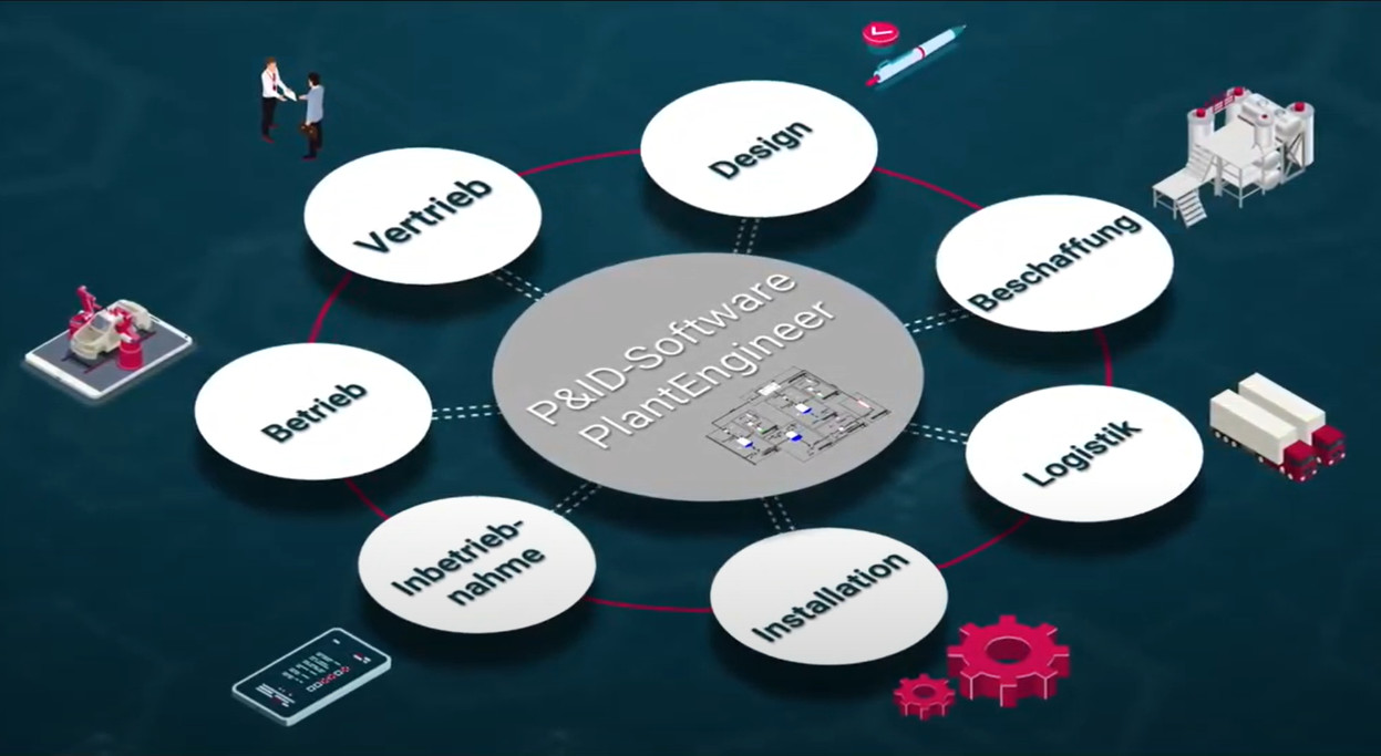
Traditionally, drawing P&IDs was left to technicians. In many companies, P&IDs are still drafted and printed in a drawing department before being corrected by the process engineer. Changes are made by hand and then updated by the drafting technician. Instead, we view the P&ID as a design document for process engineers, allowing them to make changes more quickly and avoid errors. The act of drawing gives engineers a deeper understanding of their processes.
Your flow diagrams are your business cards
Consistent communication signals a high level of professionalism. Present your sophisticated plant concepts visually with flow diagrams and symbols that comply with the ISO 10628, DIN 28000, DIN EN 62424 standards for European and Asian markets and ANSI/ISA 5.1 and PIP for American markets.
Stand out from your competition with clearly structured flow diagrams!
Advantages of the P&ID software PlantEngineer
Symbols according to international industry standards PlantEngineer includes an exhaustive collection of intelligent symbols according to the ISO 10628, DIN 2429, DIN EN 62424, ANSI/ISA, and PIP industry standards.
Easy to learn and intuitive to use The Microsoft Office-based interface allows you to create intelligent P&I flow diagrams without any CAD knowledge and with little training.
Integration into existing IT systems Interfaces according to DEXPI (Data Exchange in the Process Industry) and ISO 15926 allow two-way importing and exporting of XML data with 3D, ERPs, or simulations.
Representative reports directly from the P&ID Export component lists, ICA lists, apparatus lists, instructions, datasheets, and as-built documentation directly to Microsoft Excel and Word.
Consistent data management The central database improves project and data quality. Changes in the plant design are propagated, allowing everyone to be working with the most recent flow diagrams and reports.
High scalability Adapting to company-specific and customer-specific requirements is easy regardless of company or project size.
PlantEngineer Features
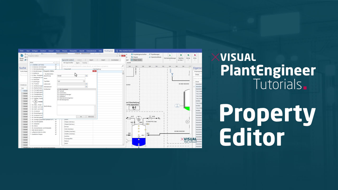
Property Editor
Create own shape properties.
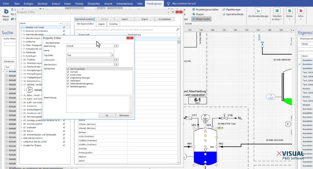
The Property Editor is a feature of the 2025 version. This function allows you to define completely new properties for your shapes. Define the name, type and visibility and simply assign the property to the corresponding shape using drag & drop.
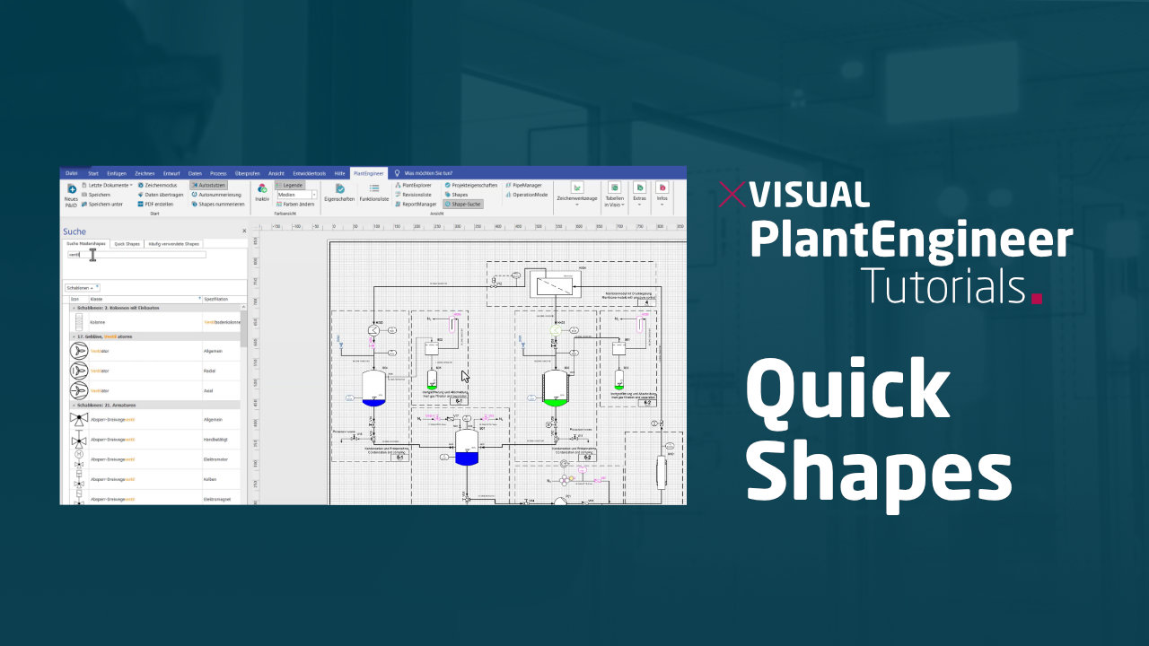
Quick Shapes
Organize important shapes.
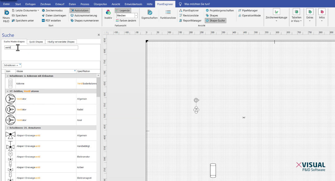
The new Quick Shapes function allows you to find important shapes quickly. Using drag & drop or a right mouse click, you can easily save shapes that you work with frequently in a favorites list. This makes it easier for you to find your most important shapes and allows you to work even more smoothly.

The Function List
Export and import data directly from the function list.
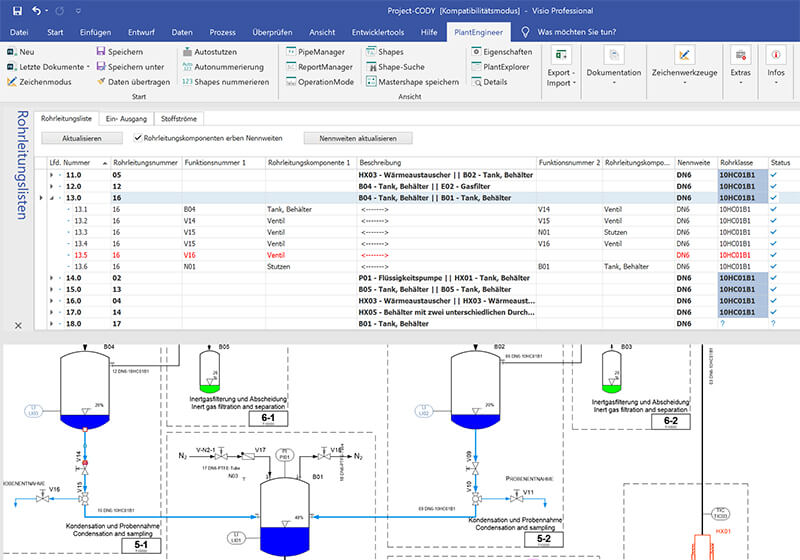
With the function list you can easily configure custom views of all shape data on the drawing.
Quickly output these lists to Excel and transfer modified data there to the drawing with one click.

Label Designer
Configure your own labels & show/hide them on the shape.
The new label feature in PlantEngineer allows you to display text information directly on the shape. With the label configurator you customize the information individually and view-related.
Decide whether you want to activate the label for all or only for selected shapes on the drawing.

Media Visualization
Add more color to your P&ID.
With the new media feature, you can visualize piping media in color according to DIN 2403 or create your own media sets in no time at all.
The media wizard allows you to quickly and intuitively create your own color schemes and media that can be used across projects and applications.

Project Assistant
Manage all projects easily and clearly.
The Project Assistant helps you manage your projects and drawings. It guides you through the creation of a new piping and instrumentation diagram, lets you edit the project data in a few clicks and helps you add a subplant within the project to the new P&ID flowsheet.
Intelligent functions for structured flowsheets
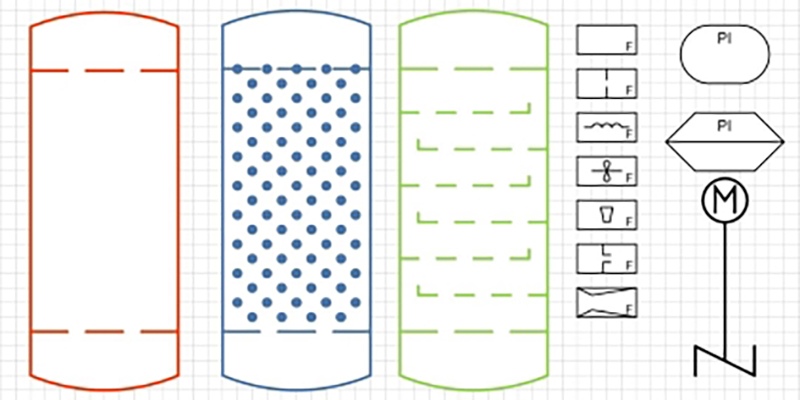
Symbols according to ISO10628, DIN28000, ANSI/ISA-5.1-2009, and PIP
Access more than 1,000 intelligent symbols form international industrial standards and create your own symbols to meet your individual requirements.
- ISO 10628 – Diagrams for the chemical and petrochemical industry
- DIN 28000 – Chemical apparatus – Documentation in the life cycle of process plants
- DIN 1861 – Refrigerating systems and heat pumps – System flow diagrams and piping and instrument diagrams
- DIN EN 12792- Ventilation for buildings – Symbols, terminology and graphical symbols
- DIN EN 62424 – Representation of process control engineering – Requests in P&I diagrams and data exchange between P&ID tools and PCE-CAE tools
- DIN 19227-1 – Control technology; graphical symbols and identifying letters for process control engineering; symbolic representation for functions
- ANSI-ISA-5.1 – Instrumentation Symbols and Identification
- PIP PIC001- Piping and Instrumentation Diagram – Documentation Criteria
Automatic identification system
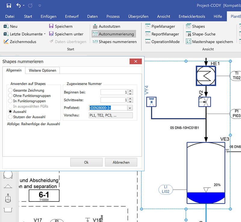
Automatic numbering makes it easier to assign and edit the plant identifiers.
- Autonumbering according to DIN28000
- Autonumbering with a dedicated numbering system
- Autonumbering for 2 numbering schemes (internal and customer numbering system)
- Modify the numbering for the entire drawing or for selected plant components
Reports in Word & Excel directly from the P&ID
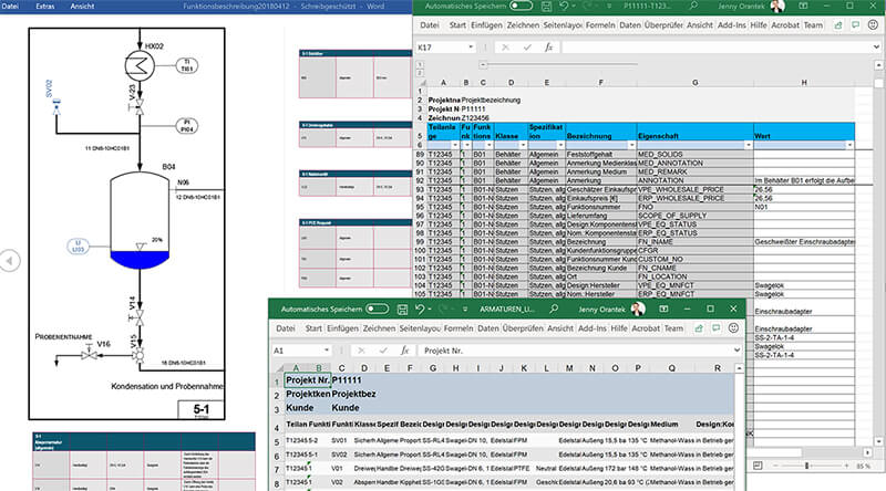
Create multilanguage lists, datasheets, instructions, and commissioning reports in Microsoft Excel or Word directly from the flow diagram.
- Each component is an object and is therefore uniquely assignable
- Component list, pipe list, apparatus list, aggregate list, electrical consumer list, ICA lists, nozzle list
- Datasheets for apparatuses, aggregates, and pumps
- System descriptions, functional descriptions, and commissioning reports
- MultiReports allows you to create more than one report at the same time
Customize reports for each customer
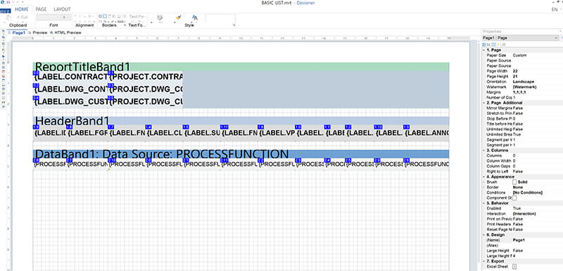
Customize your reports to meet your specific information requirements without needing any programming and create lists, datasheets, descriptions, safety descriptions in the blink of an eye.
- Easily design your reports with drag and drop
- Data representation as tables, text, graphics, and nested table elements
- Complex reports with integrated graphics and variable text elements
- Integration of external data sources (SQL, OBDC, XML, JSON)
- Integration of custom VB or C# scripts
OperationMode – Visualize and document different operating modes
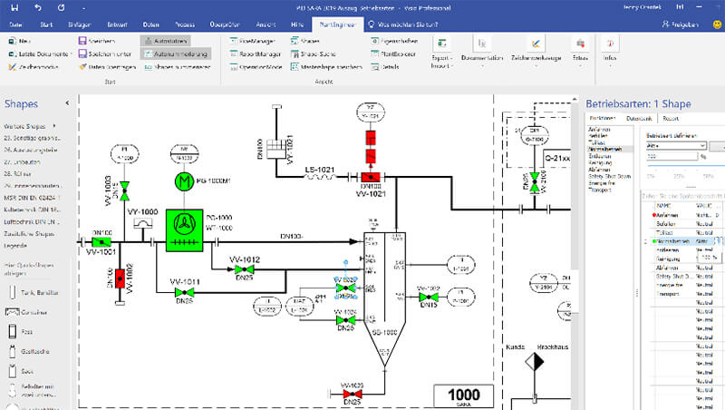
The OperationMode feature allows you to visualize and document various aspects of the plant status.
- Visualize and document the plant operating status in color (colored P&IDs)
- Status matrix in Excel for easier editing
- Status matrix provides a foundation for programming
Favoritenliste Ihrer wichtigsten Symbole
The Quick Shapes function allows you to find important shapes quickly.
Using drag & drop or a right mouse click, you can easily save shapes that you work with frequently in a favorites list .
This makes it easier for you to find your most important shapes and allows you to work even more smoothly.
Create your own P&ID flow diagram today!
All information about the different licenses and prices of our P&ID software PlantEngineer can be found in our price overview.
PlantEngineer Editions
customized to your needs
Basic
P&ID software for
professional entry
- Design P&IDs out of the box
- Export component lists in Microsoft Excel
Professional
P&ID software for professionals & freelancer
- Multilingual reports and datasheets in Microsoft Excel and Word
- Interfaces with other systems
Enterprise
P&ID software for power users
- ReportManager for comprehensive reports in Microsoft Word
- OperationMode for the visualization (colored P&IDs) and documentation of operating modes
- PipeManager for editing and validating piping systems
Academic
P&ID software for students & teachers
- Free licenses for students, pupils, teachers as well as educational institutions
- Discounted licenses for institutes and research institutions with non-commercial projects
FAQ - Frequently asked questions
Why is a representative P&ID essential for your process plant?
The P&ID is the birth certificate and life cycle document of process plant.
In plant construction projects, there are different task areas and roles with different information needs. The P&ID is the master document and the basis for a common understanding of the plant. The metadata of the P&ID can be provided for basic and detailed engineering or the installer in lists, data sheets or complete manuals.
The P&ID communicates functional relationships of process plant concepts to the customer and is already used in sales. Complex plant projects are very communication-intensive. The P&ID is the communication basis between the trades of process engineering, automation, 3D planning and electrical planning. The visual representation of the plant concept conveys the technical and functional relationships to all project participants at a glance. Integrated data graphics such as traffic lights, diagrams or colors provide a quick overview of the changes, order or commissioning status of the plant.
The Piping and Instrumentation Diagram (P&ID) is the birth certificate and life cycle document of a process plant and is subject to most changes. The P&ID accompanies the plant from initial design through commissioning, operation and maintenance.
Why do we use Microsoft Visio as a basis?
Microsoft Visio is easy and intuitive to use thanks to the Microsoft Office interface. Visio is widely used in many companies and is part of the standard. Our PlantEngineer software relies on Visio as a graphical platform, as Visio is particularly suitable for drawing schematic representations such as P&IDs.
Visio and PlantEngineer can be learned quickly without prior knowledge. We extend Microsoft Visio with a complete development environment for designing intelligent and standard-compliant P&IDs according to ISO10628 and automated documentation. Standardized, open interfaces allow integration of any data source. With PlantEngineer you get out of the box capabilities that go far beyond a simple drawing tool.
Close cooperation with the Microsoft Visio development team helps us to develop new innovative features for our customers.
You have further questions about PlantEngineer or want to solve a specific problem?
Find detailed answers to frequently asked questions in our detailed FAQ.
Do you have further questions about our PlantEngineer P&ID software or our company?
Call us, write us an email or follow us on our social media channels. The X-Visual team is looking forward to your inquiries!
